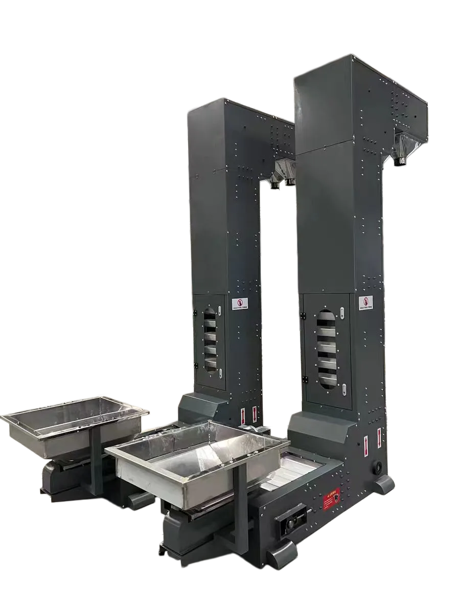
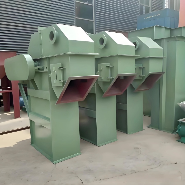
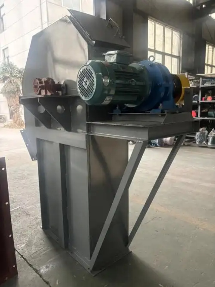
High Capacity Bucket Elevator
About the Author — This guide was written by a mechanical engineer with over 18 years of experience in bulk material handling equipment design and field commissioning across cement, mining, and grain processing facilities. Recommendations are based on hands-on analysis of over 200 elevator installations and direct troubleshooting of operational failures.
Direct Answer: A High Capacity Bucket Elevator is the right choice when your material exceeds 50 mm particle size or 1.6 t/m³ bulk density, or when you need throughput above 100 TPH. Standard elevators will fail in these conditions — leading to spillage, belt slippage, and costly downtime.
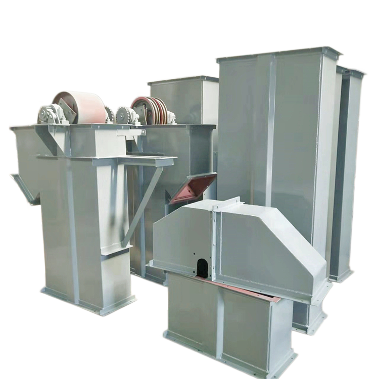
The Hidden Cost of Undersized Elevators
When a bucket elevator is undersized, the consequences extend far beyond a production bottleneck. Field observations from multiple industrial installations reveal three recurring outcomes:
Material spillage and product loss exceeding 15% when buckets are overloaded.
Belt slippage and accelerated wear from excessive traction loads — a serious ignition risk in combustible dust environments (NFPA 61).
Excessive downtime from accelerated component failure.
Based on documented cases: in one grain terminal we analyzed, repeated bearing failures from overloading resulted in 47 hours of unplanned downtime in a single season.
If particle size exceeds 50 mm or bulk density surpasses 1.6 t/m³, standard elevator designs are no longer adequate. At this threshold, a High Capacity Bucket Elevator becomes an operational necessity.
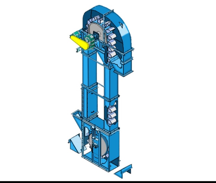
What Defines a High Capacity Bucket Elevator?
These units are purpose-engineered for extreme vertical handling, with minimum capacities starting around 100 TPH and extending to 800 TPH (some custom designs reach 2,000 TPH). Key distinguishing features:
Dual-chain systems to distribute massive loads
Larger casing dimensions — up to 82 inches wide by 66 inches deep
Heavy-duty components — head shafts up to 13″ diameter, chain ratings of 40,000 lbs
What Are the Core Technical Specifications?
The table below summarizes the key parameters. Each includes a "Selection Key" explaining how to interpret these numbers for your specific application.
| Parameter | Typical Range | Selection Key |
|---|---|---|
| Throughput | 100 – 800 TPH | Depends critically on fill factor (φ). For free‑flowing grain: φ=0.70–0.75; for sticky fly ash: φ=0.40–0.50. Ignoring this is the most common cause of capacity shortfalls. |
| Lift Height | Up to 60 m | Above 40 m, multi‑drive systems are required to reduce starting tension. |
| Head Pulley Diameter | ≥ 800 mm | Larger diameters prevent back‑legging — material falling back into the boot. |
| Casing Construction | Side plate 6–8 mm + stiffeners | Must withstand chain pull up to 40,000 lbs and bucket weights exceeding 200 kg each. |
| Inlet Chute | Flow‑in (gravity) feeding | Reduces chain loading by 15–20% compared to scoop feeding (CEMA Standard No. 301‑2018). |
Critical insight: many operators assume a 10% safety margin is sufficient. For variable feed materials, we recommend 15–20% — the cost of undersizing far exceeds the incremental cost of a larger unit.
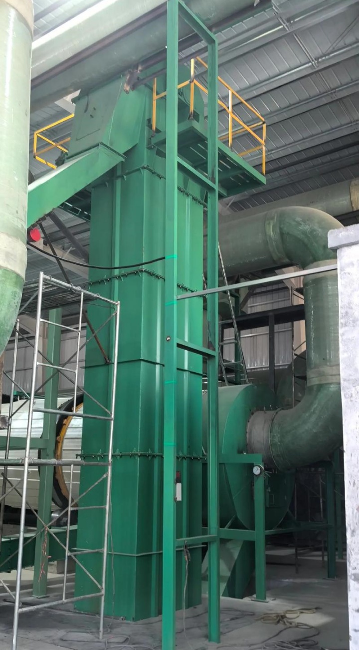
How Does a High Capacity Elevator Differ from a Standard One?
The table below compares standard and high capacity designs across four key dimensions.
| Aspect | Standard Elevator | High Capacity Elevator |
|---|---|---|
| Head Shaft Diameter | ≤ 8″ | Up to 13″ — resists bending under 40,000 lbs chain pull |
| Chain Configuration | Single strand | Dual strand — halves stress on each chain |
| Casing Support | External steel frame | Self‑supporting casing — requires PE structural analysis |
| Takeup System | Manual screw | Internal gravity takeup — self‑tensioning, leak‑proof |
What we have learned from the field: belt mistracking is corrected at the boot, not the head. We have seen countless maintenance teams waste days adjusting the wrong end.
How Do You Calculate the Required Bucket Size?
Use this industry-standard calculation (adapted from CEMA Standard No. 301):
Q = 3.6 × V × ρ × φ × i / a
Q = capacity (t/h) | V = belt/chain speed (m/s) | ρ = bulk density (t/m³)
φ = fill factor (0.40–0.75) | i = bucket volume (liters) | a = bucket pitch (m)
Worked Example — Cement (ρ=1.4, required Q=400 t/h, V=1.8, φ=0.45, a=0.5): Required bucket volume i ≈ 49 liters → select a 50-liter bucket.
| Material | Bulk Density (t/m³) | Fill Factor (φ) | Preferred Type |
|---|---|---|---|
| Cement | 1.2–1.6 | 0.40–0.50 | Chain, centrifugal |
| Coal (crushed) | 0.8–1.0 | 0.50–0.60 | Belt or chain |
| Grain | 0.7–0.8 | 0.70–0.75 | Belt, centrifugal |
| Limestone | 1.4–1.6 | 0.45–0.55 | Chain, centrifugal |
| Fly Ash | 0.6–0.8 | 0.40–0.50 | Chain, continuous |
A note from the field: calculated bucket volume is a starting point. In practice, bucket fill never reaches 100% — account for at least 10% loss due to uneven feeding and material bridging.
What Are the Top 3 Failure Modes?
1. Shaft Bending
Cause — Sudden overload (startup under full load, material jams).
Prevention — Specify shaft diameter based on maximum load; install torque limiters.
Case example: in a limestone processing operation we analyzed, repeated "flood loading" caused head shaft deflection leading to two bearing failures within three months. The specification had been based on average loads, not maximum loads.
2. Belt Mistracking
Cause — Misaligned pulleys, uneven loading, or improper takeup.
Prevention — Ensure square, level pulleys; make small incremental adjustments; specify auto-aligning idlers.
3. Dust Explosion Risk
Cause — High dust concentration + ignition source (belt slip, sparks, static).
Prevention — Comply with ATEX and NFPA standards: install explosion venting panels, sensors, and bearing temperature monitors. Conduct a Dust Hazard Analysis per NFPA 652.
Which Industries Use High Capacity Elevators?
| Industry | Materials | Recommended Configuration | Critical Considerations |
|---|---|---|---|
| Cement | Raw meal, clinker | Chain, centrifugal, abrasion liners | Temperatures up to 130°C; use AR400 alloys |
| Grain | Corn, wheat, soybeans | Belt, centrifugal, large buckets | Gentle handling — breakage below 2% |
| Mining | Ore, aggregates | Steel wire belt or heavy chain | Impact resistance at feed point |
| Fertilizer | Granular, potash | Dual‑chain, corrosion‑resistant | Use 316L stainless or coated buckets |
| Power | Coal, limestone, fly ash | Chain, centrifugal/continuous | Explosion prevention is mandatory |
| Chemicals | Powders, pellets | Material‑specific construction | ATEX compliance if combustible |
Should You Choose Centrifugal or Continuous Discharge?
| Method | Speed | Best For | Not For |
|---|---|---|---|
| Centrifugal | 1.2–2.5 m/s | Free‑flowing, coarse materials | Fragile or sticky materials |
| Continuous | 0.5–0.8 m/s | Fragile materials | High‑throughput applications |
Should You Choose Belt or Chain?
| Factor | Belt | Chain |
|---|---|---|
| Speed | High (1.8–2.5 m/s) | Moderate (0.5–1.5 m/s) |
| Max Temperature | ≤80°C | ≤150°C+ |
| Abrasion Resistance | Limited | Excellent |
| Maintenance | Lower | Higher |
| Cost | Lower initial | Higher initial |
| Best Application | Grain, feed | Cement, mining, hot/abrasive |
Rule: For abrasive, hot, or heavy materials → choose chain. For high-speed, cost-sensitive grain applications → choose belt.
What Are the Most Common Selection Mistakes?
Ignoring fill factor — Specifying based on nameplate capacity without adjusting for actual material flowability.
Underestimating chain pull — Using average load instead of maximum load calculations.
Overlooking casing rigidity — Assuming thicker steel alone solves the problem.
Neglecting explosion protection — Standard vents are often insufficient.
We have seen these errors repeatedly. A unit rated at 500 TPH for free-flowing grain may deliver only 320–350 TPH when handling sticky fly ash.
Installation and Commissioning Tips
Foundation — Must be level and capable of supporting full operating weight plus dynamic loads.
Alignment — Head and boot pulleys must be aligned within ±0.5 mm per meter of width. Use laser alignment tools.
Takeup setting — Do not over-tension initially. Run for several hours, then re-check and adjust.
Electrical — Ensure motor starters are correctly sized for starting current (6–8 times running current).
Maintenance and Service Life Extension
Weekly — Check for unusual noise, vibration, or temperature rise.
Monthly — Inspect buckets for wear; check chain pin and bushing wear.
Quarterly — Measure chain stretch; inspect sprocket tooth wear.
Annually — Perform full structural check; recalibrate safety devices.
Typical replacement intervals: buckets 3–10 years, chains 3–8 years, belts 5–10 years, bearings 2–8 years.
Frequently Asked Questions
Q1: What is the difference between centrifugal and continuous discharge?
Centrifugal elevators operate at high speeds (1.2–2.5 m/s) and are ideal for free-flowing, coarse materials. Continuous elevators operate at slower speeds (0.5–0.8 m/s) and are preferred for fragile materials.
Q2: What is the maximum capacity of a high capacity bucket elevator?
Conventional designs reach 800 TPH; custom solutions can achieve up to 2,000 TPH. Actual capacity depends heavily on bulk density, flowability, and fill factor.
Q3: How do I reduce spillage in a high-speed elevator?
Ensure buckets are filled to 65–75% of volume. Match belt speed to head pulley diameter. Design the head cover for smooth material flow without rebound.
Q4: What is the difference between self-supporting and non-self-supporting?
Self-supporting casings carry all loads directly to the foundation — no external steel needed, but require PE analysis. Non-self-supporting use external frames with simpler foundation but larger footprint.
Q5: What safety devices are mandatory?
Per NFPA and ATEX: explosion venting panels, belt slip/misalignment sensors, torque limiters, bearing temperature monitors, and ignition detection systems.
Q6: How do I calculate power requirement?
Power depends on chain pull, lift height, and efficiency. Use CEMA Standard 301 formulas. Key factors: total weight of material, buckets, and chain, plus friction losses.
Q7: Can I increase capacity of an existing elevator?
Yes — practical increases are typically 15–30% without major replacement. Upgrading may require new buckets, belt/chain, motor, shaft and bearings.
Final Selection Checklist
Material bulk density, particle size, temperature, abrasiveness measured.Fill factor determined based on flowability testing.Required throughput confirmed with 15–20% safety margin.Lift height and layout constraints documented.Discharge method chosen based on material friability.Traction system selected per material and environment.Casing support type verified with site conditions.Safety devices specified for explosion prevention.Maintenance access and future scalability considered.All applicable codes (CEMA, NFPA, ATEX) addressed.
This guide is reviewed and updated regularly to reflect the latest industry standards and field practices.
Products
Hot Modules
locations


headquarters
Address:China,Yanjin county forest park gate to the west 1000 meters north road.